A single video becomes a space in which time can be rewound.
Visualization: A technician with a headband camera connects a cable inside an opened metal housing, person, housing and wiring are freely designed | AI-assisted illustration, not a product photo | XR Stager Online Magazine | VISORIC GmbH
A technician opens the lid of a switch housing, plugs a cable into a terminal and closes the lid again. On his head he wears a camera that films everything from his perspective. A photo of the final state would later show only a closed housing. The video shows more, but every movement only from the one angle the technician happened to have.
This is exactly where a research paper comes in that appeared on the preprint platform arXiv on November 11, 2026. Leonardo Vanni, Stefano Gasperini, Federico Tombari and Chiara Plizzari describe a method that computes a three-dimensional model from a single video like this, one in which not only the space but also the change of the objects can be followed: opening, connecting, splitting and closing.[1] Experts call this 4D, three spatial dimensions plus time. The paper is a preprint and has not yet been reviewed by independent experts.
This article follows the housing example through the entire process, in eight phases from raw video to result. The example is invented, but it fits the event types of the paper. Each phase builds on the previous one and explains what happens there, why it is difficult and which numbers the paper gives for it. At the end stands the question of what companies can do with such a technique and how its benefit can be measured.
- A video from the first-person perspective is the only raw material of the method.
- The result is a 3D model that changes over time, in short 4D.
- The focus is on events in which parts separate, connect, open or close.
- The process is divided into eight phases that build on each other.
- The paper is a preprint without completed peer review.[1]
The first phase begins where every process begins, with the recording.
Capturing what a person really sees
Phase 1 of 8 · Capture
Everything begins with the raw material. Egocentric video, that is, video from the first-person perspective, is recorded with a head-mounted camera and follows the gaze of the person. For research this is a rich source: the dataset Ego4D comprises 3,670 hours of everyday video from 931 camera wearers at 74 locations in nine countries, most of it unscripted.[2] Its name combines Ego, the first-person perspective, with 4D, three spatial dimensions plus time.[2] A second dataset, EPIC-KITCHENS, collects in its original version 55 hours of kitchen routines from 32 participants, recorded in their own kitchens.[3] From both collections the paper later selects the videos for its test dataset.[1]
For reconstruction, this perspective is a problem at the same time. In the housing example there is only one camera, a so-called monocular video. It moves with the head, the person’s own hands block the view, and what lies inside the housing it only sees once the lid is open. A survey on 4D reconstruction explicitly names self-occlusion and the limited field of view of head-worn cameras as hurdles.[4]
The question is therefore not only what the camera sees, but also where it stood while doing so.

A single head-mounted camera sees a lot, but never everything.
Image: Phase 1 of the process, first-person recording at a control cabinet[2][3] | AI-assisted illustration, not a product photo | XR Stager Online Magazine | VISORIC GmbH
- Egocentric video is recorded with a head-mounted camera.[2]
- Ego4D comprises 3,670 hours of video from 931 camera wearers.[2]
- The test videos of the paper come from Ego4D and EPIC-KITCHENS.[1][3]
- A single camera delivers only one viewpoint at a time.
- Self-occlusion and a narrow field of view make reconstruction harder.[4]
Where the camera stood at each moment is clarified in the next phase.
Measuring where the camera stood
Phase 2 of 8 · Measure
Pixels only become space once it is known from where they were recorded. The second phase therefore determines, for every image, the position and viewing direction of the camera, the so-called camera pose. The method behind it is called Structure from Motion. It searches images from different viewpoints for the same features, such as the corner of a terminal, and calculates from their shifts both the position of the camera and the position of the points in space.[5] The freely available software COLMAP is widely used for this.[5]
The result is a sparse point cloud that contains only reliable features and no closed surfaces, plus a camera track that follows the technician’s head through the room. The paper assumes this preparatory work. The inputs include the video, calibrated cameras, that is, cameras with known lens parameters, masks for hands and objects, and a description of the events.[1] The test dataset delivers camera positions, camera parameters, masks and evaluation scripts right away, and according to the paper COLMAP is also used.[1] The point cloud later becomes the starting point of the actual reconstruction.
One catch remains: Structure from Motion assumes that the world stands still. If an object moves between two recordings, the method mistakes object motion for camera motion. With the housing in the technician’s hand, exactly this happens. Before the reconstruction can begin, it is therefore necessary to separate what rests from what moves.
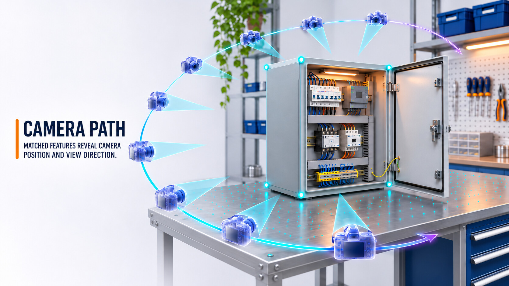
From features in many images, the path of the camera through space emerges.
Image: Phase 2 of the process, camera path around a control cabinet and sparse point cloud[1][5] | AI-assisted illustration, not a product photo | XR Stager Online Magazine | VISORIC GmbH
- Every image needs a known camera position made up of location and viewing direction.
- Structure from Motion calculates it from features that recur in several images.[5]
- COLMAP is a freely available, widely used software for this step.[5]
- The inputs of the paper comprise video, calibrated cameras, masks and event specifications.[1]
- Moving objects disturb the measurement and must be separated beforehand.
How this separation succeeds is shown in phase three.
Separating what rests from what moves
Phase 3 of 8 · Separate
In the housing example there are three roles in the picture: the table and the room, which stand still, the housing, which moves, and the hands that move it. The third phase assigns one of these roles to every image region. For this, a mask is created for each image, a kind of stencil that marks where an object lies in the image. The paper generates object and hand masks with SAM 3, a model from Meta released in November 2025 that finds objects in images and short videos from a text term or an example image, outlines them and follows them over time.[6] All generated masks were subsequently checked by hand.[1]
The second idea of this phase comes from a predecessor method on which the paper builds. EgoGaussian, developed at ETH Zurich, divides a video into calm and moving segments. From the calm segments the background emerges and the shape of the object is prepared. In the moving segments the object is refined and its motion tracked.[7] The hands are not reconstructed along with it. To keep the comparison fair, the paper applies this masking to the competing methods as well.[1]
EgoGaussian does, however, make an assumption that becomes a problem for the housing: it tracks rigid objects that move as a whole and neither deform nor break into parts.[7] A lid that detaches from the housing does not fit this picture.

Only when background, object and hands are separated can each be reconstructed on its own.
Image: Phase 3 of the process, moving housing in front of a still background and a timeline of resting and moving segments[1][6][7] | AI-assisted illustration, not a product photo | XR Stager Online Magazine | VISORIC GmbH
- Masks mark in each image where hands, object and background lie.
- SAM 3 finds and tracks objects from a text term or example image.[6]
- The masks of the paper were checked by hand.[1]
- EgoGaussian divides the video into calm and moving segments.[7]
- The predecessor method tracks only rigid objects that do not break into parts.[7]
What happens with these separated parts depends on how a space is represented in the computer in the first place. Phase four explains that.
Building a space from dots of color
Phase 4 of 8 · Build
The fourth phase builds the actual model. Gaussian Splatting, introduced in 2023 by a team around Bernhard Kerbl, represents a scene with very many small, semi-transparent ellipsoids called Gaussian splats. Each splat has a position, a shape, a transparency and a color.[8] The starting point is the sparse point cloud from the measuring phase.[8] The image is formed by sorting all splats that cover a pixel by depth and blending them. This works so fast that scenes can be displayed at at least 30 frames per second in Full HD resolution.[8]
Learning happens in an interplay: the system renders an image, compares it with the real video frame and corrects the position, shape and color of the splats. Where the image still does not match, it adds splats or removes some.[8] In the end stands a model that can be viewed from any angle, not only from that of the camera.
A splat model is, however, initially a still image. For moving scenes, 4D Gaussian Splatting was developed. The method by Guanjun Wu and colleagues keeps a single set of splats and learns a small neural network that specifies for every point in time where the splats move and how they deform.[9] On synthetic test data it renders up to 82 frames per second at 800 by 800 pixels.[9] This is elegant as long as the same things merely move. The set of splats is fixed, no new ones are added and none disappear.

A Gaussian splat is small, but many of them form a space that can be viewed freely.
Image: Phase 4 of the process, a control cabinet as a model of Gaussian splats, from rough to refined state[8][9] | AI-assisted illustration, not a product photo | XR Stager Online Magazine | VISORIC GmbH
- A scene consists of many Gaussian splats with position, shape, transparency and color.[8]
- The model learns by comparing rendered images with real video frames.[8]
- Display works in real time, at at least 30 frames per second in Full HD.[8]
- 4D Gaussian Splatting moves a fixed set of splats through time.[9]
- New surfaces cannot emerge in this approach because no splats are added.
Exactly this fixed setup becomes a problem when a lid is opened. Phase five shows where the concept breaks.
When an object splits, connects, opens or closes
Phase 5 of 8 · Break
In the housing example, now happens what 4D methods fail at. The lid opens, the interior becomes visible. The cable connects two previously separate parts. The lid closes, the interior disappears. The paper calls such processes topological events: time-limited actions that change how parts of an object are connected, how they move or which surfaces are visible.[1] It distinguishes four families. In fission, an object splits, for example when cut. In fusion, parts connect, for instance by plugging in, screwing on or knotting. In opening, surfaces are exposed, for instance by opening up or uncovering. In closing, they disappear again, for instance by shutting or covering.[1] The image shows the four families on the housing in this order: lifted lid, connected cables, opened door and closed housing again.
For a model with a fixed set of splats, such events are a tall order. Because the method only deforms what is already there, events that split, connect or expose surfaces lead to severe image errors.[1] For the interior of the housing there are simply no splats that could move there. The survey on 4D reconstruction counts topological changes such as splitting and joining objects among the dynamic phenomena that remain largely unsolved.[4]
Before this can change, the method must know what is happening in the first place. Topo-4DGS, short for topology-aware 4D Gaussian Splatting, receives an event specification for this: the event family, the number of resulting end pieces, the parent-child structure of the parts as a kind of family tree, and the point in time from which the parts may move independently.[1]

Four event families change which surfaces an object has, and with that the core of the model.
Image: Phase 5 of the process, the four event families fission, fusion, opening and closing on the example housing[1][4] | AI-assisted illustration, not a product photo | XR Stager Online Magazine | VISORIC GmbH
- Topological events change the connectivity, motion or visible surfaces of an object.[1]
- The paper distinguishes fission, fusion, opening and closing.[1]
- Methods with a fixed set of splats produce severe image errors at such events.[1]
- Topological changes are considered largely unsolved in the survey.[4]
- Topo-4DGS needs event family, end pieces, family tree of the parts and event time as input.[1]
How Topo-4DGS works with this input is the topic of the sixth phase.
Branching, how an object falls into parts
Phase 6 of 8 · Branch
The sixth phase is the heart of the paper. Topo-4DGS solves the problem in two steps that together move the parts and adapt the surfaces.[1] The first step is called Motion Bifurcation. Until the event, the object moves as one rigid whole. From the event on, this single motion branches into several branches, each with its own rigid motion.[1] In the example, the housing travels on in one hand while the lid follows another path. For this, each splat is assigned to a branch.[1]
The second step, Topological Boundary Resolution, adapts which surfaces exist. When the housing is opened, new, previously hidden surfaces emerge. For this, splats are created that become active exactly at the time of the event. When it is closed, surfaces disappear from view and the associated splats are switched off.[1] With fission and opening, surfaces are thus added, with fusion and closing they are withdrawn.[1] The paper describes two building blocks for this: the construction of the boundary surfaces per part and the temporal activation of the splats.[1]
The ablation experiments, in which building blocks are changed or left out, show how much depends on the specifications. If the assignment of parts is allowed to change arbitrarily from frame to frame, the quality of the post-event images drops by more than 7 decibels.[1] If the event time is set 16 frames too early, the quality of the object falls by 0.47 decibels, if 16 frames too late by 1.26.[1] The method achieves its largest gains on separation events, that is, opening and fission.[1] A limit is set by the assumption of rigid parts: Topo-4DGS targets time-limited changes whose resulting parts can be approximated as rigid.[1]

Two mechanisms work together: the motion branches, and the surfaces are switched on or off.
Image: Phase 6 of the process, motion branching (top) and temporal activation of the exposed interior surface (bottom) in Topo-4DGS[1] | AI-assisted illustration, not a product photo | XR Stager Online Magazine | VISORIC GmbH
- Motion Bifurcation splits a rigid motion into several branches from the event on.[1]
- Boundary resolution activates new surfaces and deactivates hidden ones.[1]
- Arbitrarily changing part assignment costs over 7 decibels on the post-event images.[1]
- An event time shifted by 16 frames lowers the quality by 0.47 to 1.26 decibels.[1]
- The method assumes parts that can be approximated as rigid.[1]
Whether the method actually works better than previous approaches is examined in the seventh phase.
Testing, how good is good
Phase 7 of 8 · Test
A method is only as meaningful as its test. For the paper there was no suitable one: no benchmark systematically tested fission, fusion, opening and closing in egocentric videos.[1] The authors therefore built TopoEgo. The dataset contains 24 sequences from EPIC-KITCHENS and Ego4D, twelve from each source, with 36 moving objects, 34 marked events and around 4,600 individual frames. Three clips were selected per event family and source. The events were annotated and checked by hand, and camera positions, masks and evaluation scripts are included.[1]
Measurement works by having the system render images it has not seen during training and comparing them with the real video. Four metrics describe the distance, and the table shows them together with the lead of Topo-4DGS over EgoGaussian on the moving objects across all 24 clips.[1][10]
| Metric | What it measures | Better is | Difference to EgoGaussian |
|---|---|---|---|
| PSNR | Pixel error relative to the real image, in decibels | higher | +3.19 dB |
| SSIM | Similarity of brightness, contrast and structure | higher | +0.094 |
| LPIPS | Perceptual similarity, computed with a neural network | lower | −0.036 |
| α-IoU | Overlap of object outlines | higher | +0.110 |
On the moving objects, all four metrics favor Topo-4DGS.
Table: Evaluation metrics and results of Topo-4DGS compared with EgoGaussian on 24 TopoEgo clips, moving objects[1][10] | XR Stager Online Magazine | VISORIC GmbH
A rule of thumb helps with interpretation. For PSNR, roughly 3 decibels mean that the mean squared pixel error is halved.[11] On the images after the event the lead is 4.47 decibels, which corresponds computationally to roughly a factor of 2.8 in the error.[1][11] The absolute values put this into perspective: across all clips, Topo-4DGS reaches 21.74 decibels in the object region.[1] By a common rule of thumb, deviations in the range of 20 to 30 decibels remain visible.[11] The model is better than its predecessors, but not yet a true copy.
Four caveats belong here. First, on the entire scene, that is, including the background, a competitor is ahead: Def-3DGS achieves the best means for PSNR, SSIM and LPIPS there, and DeGauss has a lower LPIPS than Topo-4DGS.[1] The advantage applies to the moving objects. Second, a clip takes a median of 10.9 hours on an A100 graphics card, with a range of 3.6 to 22.8 hours, about 1.28 times that of EgoGaussian.[1] Third, rankings can shift: an independent re-evaluation from 2026 reached different results for EgoGaussian and its comparison methods than the original work.[12] Fourth, the paper is a preprint, and code and data are announced.[1]

Sharp edges and consistent details decide whether a model appears reliable.
Image: Phase 7 of the process, blurred model on the left versus sharp result on the right, detail comparison at a lid edge[1][10] | AI-assisted illustration, not a product photo | XR Stager Online Magazine | VISORIC GmbH
- TopoEgo comprises 24 sequences, 36 moving objects and 34 marked events.[1]
- On moving objects, Topo-4DGS is ahead of EgoGaussian on all four metrics.[1]
- On the images after the event, the PSNR lead is 4.47 decibels.[1]
- On the entire scene, Def-3DGS is ahead in the means.[1]
- The compute time is a median of 10.9 hours per clip.[1]
What can be derived from these numbers for practice is brought together in the last phase.
Benefit, where a 4D model could help in practice
Phase 8 of 8 · Benefit
The last phase asks about value. The paper itself names embodied AI, that is, AI that acts in the physical world, as its motivation.[1] For companies, other applications are closer at hand. A 2026 publication from the Fraunhofer publication repository describes that assembly and disassembly processes rely on expert knowledge that is hard to document, reuse and pass on. Video-based representations capture sequence and execution context better than static images, with repair, training and circular economy named as examples.[13] A 4D model would preserve the housing example not as a film but as a space: pause, rotate, look inside, inspect the critical moment from the best angle. This is an editorial assessment. A benefit for training is not proven in the sources reviewed here.
Three things still stand in the way of deployment. The first is the event specifications. An automatic module that estimates them from the video named the correct number of parts for 26 of 36 objects, that is 72.2 percent, and the correct event family for 16 of 24 objects, that is 66.7 percent. It works with a vision-language model that looks at twelve frames of the masked object, and is a standalone preprocessing tool, not part of Topo-4DGS. The benchmark results rely on specifications checked by hand.[1] The second is the assumption of rigid parts, soft, liquid or elastic things lie outside.[1] The third is time and availability: a good ten hours of compute per clip, plus code and data that are announced but not yet released.[1]
How a benefit can be tested is thus the real question. A 4D model can look convincing without anyone learning from it, because PSNR measures similarity to the image, not the understanding of a task. A robust test asks for the learning outcome: does training with the model lead to fewer execution errors, shorter processing time, better retention after several weeks? How procedural errors can be captured is shown by the dataset IndustReal with 84 videos and 38 execution errors in the assembly and maintenance of a toy car.[14] A plausible first test would be small: one procedure, one reconstruction, a comparison with a group that learns conventionally.
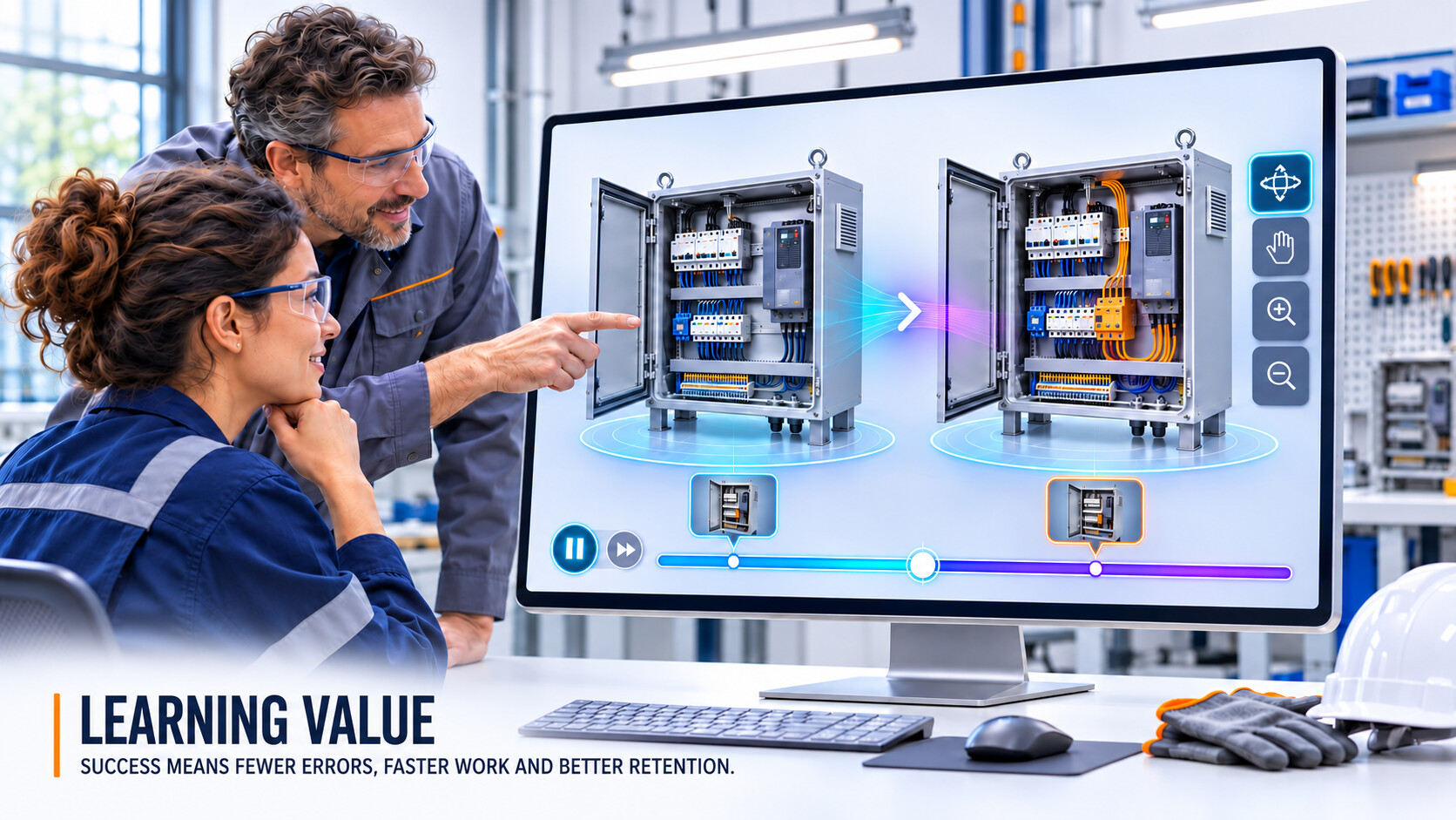
The value of a 4D model shows not in the image, but in the learning success afterwards.
Image: Phase 8 of the process, a 4D model as a learning aid in assembly, maintenance and training[13][14] | AI-assisted illustration, not a product photo | XR Stager Online Magazine | VISORIC GmbH
- Assembly, maintenance and training are considered obvious fields of application.[13]
- A benefit for training has so far not been proven in the sources reviewed.
- The automatic event estimation was correct in 72.2 and 66.7 percent of cases.[1]
- Metrics for a test are error rate, processing time and retention after weeks.
- A small first comparison with a conventionally learning group is the sensible start.
What the principle looks like in motion is shown in the following video.
The principle in 41 seconds
The preceding phases have explained how a video becomes a model that changes over time. The following video puts the same idea into images: an object is handled, and the reconstruction follows the change. The film is an explanation by the author, not a recording from the paper. The images are AI-generated and show the principle, not measurement results. The numbers and results are in the paper.[1]
Video: Explainer film on the paper Topology-Aware 4D Gaussian Splatting for Egocentric Videos | Film concept, research, analysis and narrator: Ulrich Buckenlei | Illustrative images: AI-generated | Research: Vanni et al.[1] | XR Stager Online Magazine | VISORIC GmbH
- The video explains the core idea of the paper in 41 seconds.
- It shows how a video recording becomes a model with a time dimension.
- The images are AI-generated and purely illustrative.
- Concept, research, analysis and narrator come from Ulrich Buckenlei.
- The underlying research comes from Vanni et al.[1]
Between a research demo and a robust learning environment lies a path of testing, and it begins with a clearly defined first step.
From reconstruction to a robust learning environment
In every company there is a skill that only a few specialists truly master: a maintenance task, an assembly, a commissioning. Today it may exist as a video that everyone sees only from the one angle of the camera. As a space with a time dimension, it could be viewed from all sides, paused and rewound. An impressive reconstruction only becomes training when three things come together: a method that can be tested, a model that fits into existing systems, and a test that measures learning success and error rate.
The expert team of VISORIC GmbH from Munich combines over 15 years of experience in 3D, AI and XR with practical experience in spatial computing, real-time 3D and digital twins. VISORIC classifies new methods such as Gaussian Splatting, examines what of them holds up for training and digital twins, and supports companies from the first idea to a deployable application. Together with you, the team clarifies which skill is suited for getting started, prepares it and measures what your employees learn from it.[15][16]

15 years of experience in 3D, AI and XR: the VISORIC expert team from Munich.
Image: © Ulrich Buckenlei | XR Stager Online Magazine | VISORIC GmbH
A well-conceived pilot project with a single process and a clearly defined learning environment can often be realized much faster and more cost-effectively than many companies expect. Getting started consists of three steps:
- Selecting a process for the first trial, such as a maintenance task, an assembly or a commissioning.
- Preparing it as a digital twin or XR training in which the process can be paused, rotated and repeated.
- Measuring error rate, processing time and retention before deciding on an expansion.
This is exactly the starting point for a conversation: not the big, company-wide vision, but a clearly defined first step that can be implemented quickly.
Which process in your company would be worth not only being filmed, but understood as a space with a time dimension?
Talk to the VISORIC expert team from Munich about spatial computing, digital twins and XR training. Together we will turn your process into a precise, traceable next step.
Contact:
Email: info@visoric.com
Phone: +49 89 21552678
Sources and references
- Vanni, Gasperini, Tombari, Plizzari. Topology-Aware 4D Gaussian Splatting for Egocentric Videos. arXiv:2611.16012, preprint, November 11, 2026. Project page topoego.github.io.
- Grauman et al. Ego4D, Around the World in 3,000 Hours of Egocentric Video. CVPR 2022, arXiv:2110.07058.
- Damen et al. Scaling Egocentric Vision, The EPIC-KITCHENS Dataset. ECCV 2018, arXiv:1804.02748.
- Reconstructing 4D Spatial Intelligence, A Survey. arXiv:2507.21045, 2025.
- Schönberger and Frahm. Structure-from-Motion Revisited. CVPR 2016. COLMAP documentation, colmap.readthedocs.io.
- Carion et al. SAM 3, Segment Anything with Concepts. Meta, arXiv:2511.16719, November 2025, ICLR 2026.
- Zhang et al. EgoGaussian, Dynamic Scene Understanding from Egocentric Video with 3D Gaussian Splatting. arXiv:2406.19811, 3DV 2025.
- Kerbl, Kopanas, Leimkühler, Drettakis. 3D Gaussian Splatting for Real-Time Radiance Field Rendering. ACM Transactions on Graphics 42(4), 2023.
- Wu et al. 4D Gaussian Splatting for Real-Time Dynamic Scene Rendering. CVPR 2024.
- IEEE Technology Navigator. PSNR, Peak Signal-to-Noise Ratio, overview of definition and limits. technav.ieee.org.
- Forasoft. PSNR explained, definition, formula and value ranges. forasoft.com, as of November 2026.
- Bringing a Personal Point of View, Evaluating Dynamic 3D Gaussian Splatting for Egocentric Scene Reconstruction. Independent re-evaluation, arXiv:2604.23803, 2026.
- Chavan. AI-based worker guidance in assembly and disassembly operations using multimodal ego/exo-centric data capture and structured task knowledge. Fraunhofer-Publica, 2026.
- Schoonbeek et al. IndustReal, Dataset of Egocentric Videos for Procedure Understanding. arXiv:2310.17323, 2023.
- VISORIC practical projects in the fields of digital twins, real-time 3D and spatial computing.
- XR Stager platform for real-time 3D, digital twins, Knowledge AI and industrial spatial computing applications.
Contact Us:
Email: info@xrstager.com
Phone: +49 89 21552678
Contact Persons:
Ulrich Buckenlei (Creative Director)
Mobil +49 152 53532871
Mail: ulrich.buckenlei@xrstager.com
Nataliya Daniltseva (Projekt Manager)
Mobil + 49 176 72805705
Mail: nataliya.daniltseva@xrstager.com
Address:
VISORIC GmbH
Bayerstraße 13
D-80335 Munich