For decades, approximation was considered a flaw. AI turns it into a method. What that means for everyone who works with simulation today or will soon.
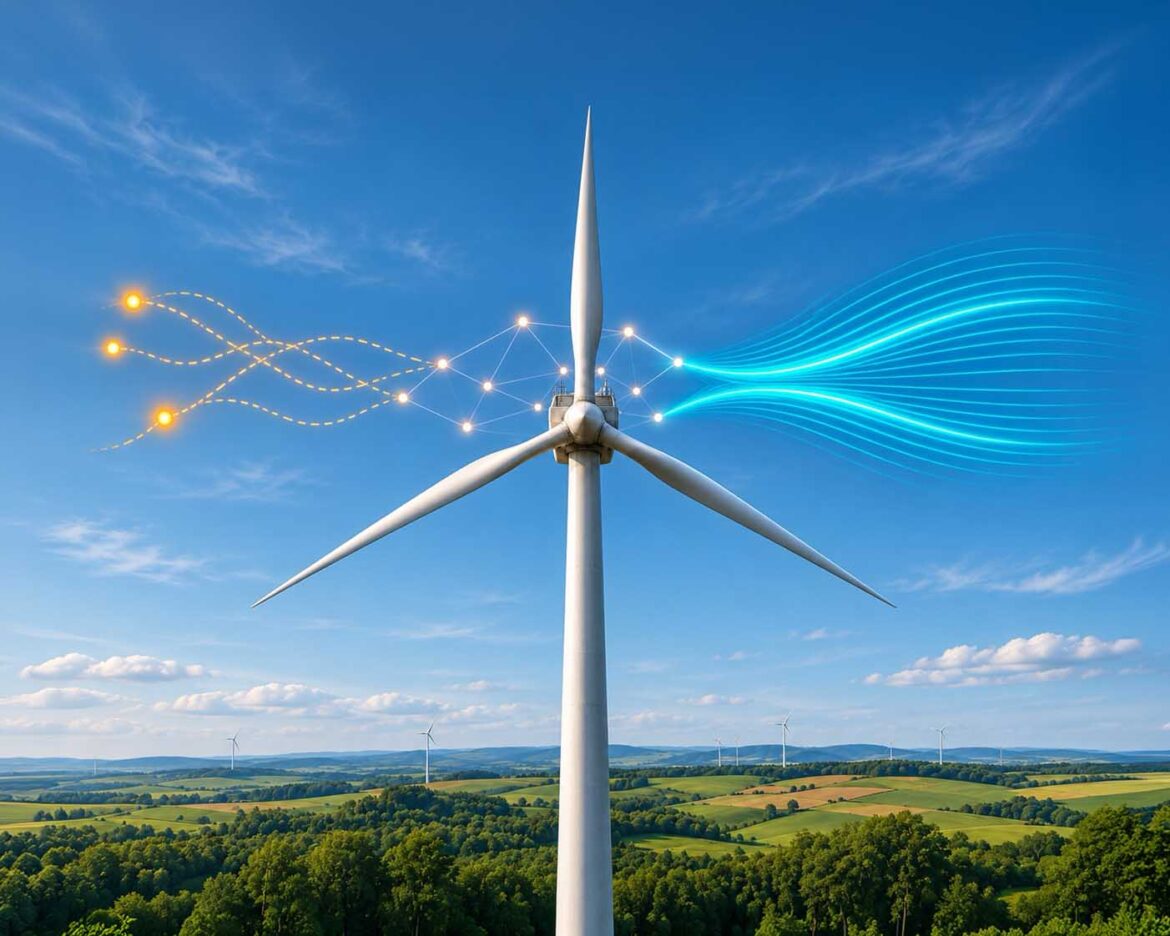
Illustration: Wind turbine with overlaid simulation layers: particle model (Lo-Fi / VFX), AI Surrogate Network (inference layer), and physical flow lines (CFD reference) — three validation levels in one representation | VISORIC Newsroom | VISORIC GmbH
There are verdicts in engineering that have held so long that people have stopped questioning them. One of them reads: either you simulate with physical accuracy, or you simulate for the presentation. There is nothing reliable in between.
The verdict arose from a genuine opposition. On one side stands CFD, Computational Fluid Dynamics: numerical flow simulation that solves physical equations step by step — computationally intensive, precise, and robust enough for standards, approvals, and certifications. On the other side stand real-time visualization systems, called Lo-Fi because they are physically plausible but have no validatable physical core: fast, interactive, visually convincing. The technical term Hi-Fi denotes the opposite — full physical accuracy at the cost of time and computational effort. Between these two poles, there was nothing for decades. Either Lo-Fi or Hi-Fi. Either the image or the truth.
This verdict was justified as long as no third option existed.
AI fills this space. Not by making approximation models more precise. But by giving them something they never had: a quantifiable physical foundation. The idea is called an AI Surrogate Model: a neural network trained on thousands of real CFD simulation runs that can compute new scenarios in real time, because it has internalized the solution spaces of physical equations without having to recalculate them from scratch for every query. That sounds like a technical improvement. It is a methodological shift.
This article describes what this shift means, where its limits lie, and what consequences it holds for everyone who works with simulation in development, planning, or Digital Twin architecture.
- The space between Lo-Fi visualization and Hi-Fi CFD was methodologically empty for decades. AI fills it.
- AI Surrogate Models do not deliver precision — they deliver a quantifiable approximation with a physical foundation.
- Three validation levels structure which method answers which question.
- The genuinely new competency is not the tool, but the matching of method to decision requirement.
- CFD remains indispensable. But its scope of application is now more sharply defined.
The first chapter begins where the verdict originated: at the beginnings of computer simulation.
How the Verdict Arose: Two Cultures, One Continuum
Computer-aided fluid simulation did not emerge in the 1960s as a tool, but as a promise. The promise was: physical reality can be translated into numbers — reproducible, verifiable. CFD was a precision instrument from the start. Not because it was convenient, but because it had no other reason to exist.
Thirty years later, real-time visualization systems emerged for film and game development. Fire, smoke, explosions, liquids: spectacular and fast. Physical accuracy was never the goal here. The goal was: it has to look convincing, in real time, on screen. Two disciplines claiming the same continuum, but from opposite ends.
The separation was structurally grounded. Behind it lay a technical reality: grid-based visualization systems lose energy systematically during numerical integration. This is called numerical dissipation. For visually convincing results, it is irrelevant. For physical validation, it renders results unusable, because deviations from the real model are not predictable. CFD solvers addressed this problem through elaborate mesh refinement and higher-order computation. Visualization systems did not, because they did not need to.
The result was binary thinking. Either you have a valid simulation result or you have a pretty picture. No third option existed. Whoever had to forgo CFD resources in early planning phases worked with what remained: images that convinced without proving.

Three eras, three guiding principles: physical truth, visual conviction, data-driven inference.
Illustration: Evolution of simulation methods from CFD (1960s) through real-time VFX (1990s) to AI-powered Surrogate Models today[4][5] | AI-assisted illustration, not a product photo | VISORIC Newsroom | VISORIC GmbH
What AI changes is not the precision of approximation. It is its status. An AI Surrogate trained on validated CFD data is not a better visualization. It is a different class of result: an approximation with a traceable physical origin, whose deviation from the real model is fundamentally describable. That does not make the decades-old verdict wrong. But it differentiates it.
- CFD emerged as a precision instrument with a clear claim to truth.
- Real-time visualization systems prioritized visual conviction, not physical accuracy.
- Numerical dissipation is the technical reason for the decades-long separation of these two worlds.
- AI does not change the precision of approximation models — it changes their methodological status.
- The binary thinking of valid or pretty now has a third option.
What this third option concretely delivers — and what it cannot — is the subject of the next chapter.
Real Time and Its Limits: What Visualization Systems Can Do
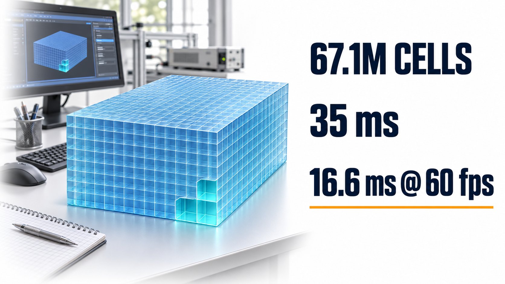
Modern real-time visualization systems for physical phenomena have reached a performance threshold in recent years that would have been unthinkable a decade ago. Current GPU-based systems compute voxel grids with over 67 million cells in under 40 milliseconds. This means: an engineer can observe in real time how a smoke or flow scenario develops under changed parameters. Obstacle geometries can be adjusted, wind speeds varied, heat sources shifted, and the effects seen immediately.
This is not a small advance. It represents access to an understanding of physical systems that simply did not exist in early planning phases. Anyone who wants to communicate a ventilation concept for an industrial hall, persuade stakeholders on a wind load scenario, or understand early on which geometry is even worth pursuing — these are insights that previously required CFD runs first.
The limit is precisely nameable. Voxel-grid methods are subject to numerical dissipation. This means: the model systematically loses energy at each time step. The results are physically plausible. They are not physically validatable in the sense of standards and certification. Fire evacuation plans, ventilation design to EN standards, structural wind load calculations for permit applications: these are questions that require a different method.
67 million voxels in under 40 milliseconds: the performance limit of modern GPU-based visualization systems — and the boundary of their physical validity.
Illustration: Voxel-grid performance of current real-time visualization systems. 35 ms/step, ~1.9 billion voxels/second GPU throughput. 16.6 ms = compute budget at 60 fps[1][2] | AI-assisted illustration, not a product photo | VISORIC Newsroom | VISORIC GmbH
The right question is not: Is this good enough? The right question is: good enough for what? For early exploration of geometries, for communicating a concept in a planning meeting, for intuitive understanding of a physical system: yes. For decisions that require physical validation: no. This distinction is not technical trivia. It is the core of a methodological competency that becomes more important in the AI era, not less.
| Criterion | Real-Time Visualization (Lo-Fi) | CFD (Hi-Fi) |
|---|---|---|
| Computation Time | Milliseconds (real time) | Hours to days |
| Physical Foundation | Plausible, not validatable | Validatable (Navier-Stokes) |
| Standards Compliance | No | Yes (EN, DIN, ISO) |
| Strength | Exploration, communication, concept decisions | Safety, approval, certification |
Same domain, fundamentally different validation requirements: real-time visualization and CFD are not competitors — they are tools for different questions.
Table: Editorial comparison of Lo-Fi real-time visualization and CFD by technical and application criteria[1][2] | VISORIC Newsroom | VISORIC GmbH
- Current GPU systems achieve real-time performance with over 67 million voxel cells.
- Numerical dissipation makes voxel-grid results unsuitable for physical validation.
- The value lies in real-time interaction: parameter variations immediately visible and comprehensible.
- The key question is not good enough, but: good enough for what?
- The distinction between plausibility and validatability is methodological, not technical.
The next chapter describes the greatest risk that accompanies this visual capability.
The Plausibility Trap: When the Image Promises More Than the Method Can Deliver
There is a risk that arises with the growing visual maturity of simulation results and that is rarely openly named. It is this: the results look too good.
When a smoke-spread rendering from a visualization system on the presentation screen can no longer be distinguished from a CFD result, a cognitive problem emerges. Human judgment is not trained to tell the two apart. Trust is generated by appearance, not by method. And the trust that a visually convincing result creates is often greater than what the underlying method actually justifies.
This is the plausibility trap. It is not a technical failure. Nobody is using the tool incorrectly. The trap forms at the moment of classification: when a result that is suitable for concept decisions carries decisions that require physical validation. This can happen because the distinction was not communicated. It can happen because stakeholders are not aware of it. And it can happen because time pressure tempts teams to declare the available image sufficient.
The consequence is not to avoid visualization. The consequence is to label it transparently. Results must be communicated with their validation level — not only internally, but also to everyone who makes decisions based on them. A concept image is a concept image. It can carry concept-level decisions. It must not carry decisions for which standards, authorities, or approval bodies expect physical validation.
Visually nearly indistinguishable, methodologically fundamentally different: concept visualization and CFD validation look equally convincing on the presentation screen.
Illustration: Plausibility trap. The difference between Lo-Fi visualization (concept level) and CFD (safety validation) lies not in appearance but in validation depth[3][6] | AI-assisted illustration, not a product photo | VISORIC Newsroom | VISORIC GmbH
Methodological transparency is not a weakness. It is the prerequisite for the strengths of each method to be used at all. Communicating a Lo-Fi result as such does not diminish it. It makes it usable.
- The visual maturity of results and their physical robustness are not the same thing.
- The plausibility trap does not arise from technical failure, but from methodological misclassification.
- Results must be communicated with their validation level — internally and externally.
- Methodological transparency is a prerequisite for the legitimate use of Lo-Fi methods.
- A concept image communicated as a concept image is stronger than one passed off as proof.
The next chapter explains what AI Surrogate Models are and why they do not eliminate the plausibility trap but shift it.
What AI Surrogate Models Can Do: The New Middle Level
Between Lo-Fi visualization and Hi-Fi CFD, a third method exists today. It has no universally accepted name. Depending on context, it is called an AI Surrogate, neural emulator, or data-driven model. What it is can be described most easily by what it is not: it does not solve physical equations in real time. And it is not an upgraded visualization system. It is the result of a learning process over physical data.
How a surrogate is created. The foundation consists of thousands of CFD simulations of a specific physical phenomenon. Flow profiles around rotor blades. Smoke spread in defined hall geometries. Thermal distributions across production lines. A neural network is trained on this data — one that learns not only the data, but the physical laws behind it. This approach is called Physics Informed Machine Learning. The trained model can evaluate new parameter combinations, modified geometries, and different operating conditions in milliseconds. Not because it solves the CFD equations. But because it has internalized their solution spaces.
This is the methodological difference. A classical visualization is physically plausible. An AI Surrogate is physically grounded. It has a provenance: validated CFD data. And it has a describable domain of validity: the parameter space for which it was trained. Within this space, its predictions carry a quantifiable deviation from the physical model. That is fundamentally different from numerical dissipation without reference.
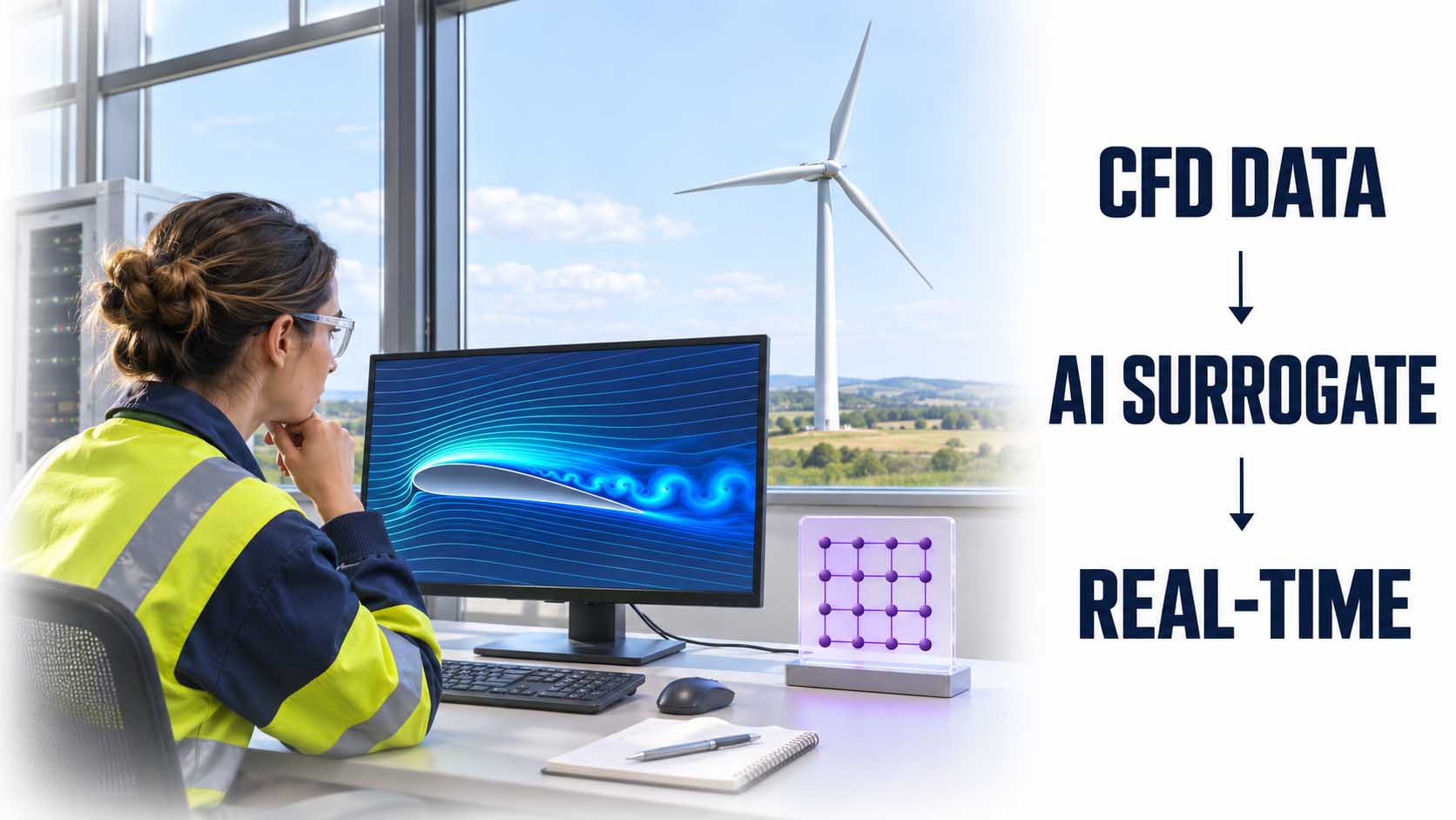
The surrogate pipeline: CFD data is used to train a model that subsequently computes new scenarios in real time, without routing every run through the full solver.
Illustration: AI Surrogate Pipeline. CFD dataset → Training (Physics Informed Machine Learning) → Real-time inference for new scenarios. Platform example: NVIDIA Modulus[5][7] | AI-assisted illustration, not a product photo | VISORIC Newsroom | VISORIC GmbH
The new form of the plausibility trap. A surrogate model degrades outside its training domain — and this does not always happen visibly. Anyone who extrapolates a trained model into parameter ranges for which no training data exists receives results that look physically convincing but are physically unreliable. The trap shifts. It does not disappear.
- AI Surrogate Models learn the solution spaces of physical equations instead of recalculating them for each query.
- Physics Informed Machine Learning anchors the model in physical laws.
- The domain of validity of a surrogate is describable: the parameter space of the training data.
- Within this domain, deviations from the physical model are fundamentally quantifiable.
- Outside it, the model degrades — often without this being immediately visible.
The next chapter describes how the three methods interact within a structured model.
Three Levels, One Logic: Method Follows the Question
The rehabilitation of approximation is not a free pass. It is a differentiation. And this differentiation can be described in a model that is simple enough to use in development conversations and precise enough to prevent poor decisions.
Level 1: Concept. Which geometry is promising? Which scenario illustrates the concept for the conversation with the client? Which variants should be pursued at all? Real-time visualization systems work here: fast, intuitive, physically plausible. The results support concept-level decisions. Time horizon: hours.
Level 2: Design. Which of the three variants performs better in the flow profile? Is the ventilation design sufficient for normal operation? How does the model behave under changed operating conditions? AI Surrogates work here: physically grounded, fast enough for iterative parameter studies, reliable within the training domain. Time horizon: days.
Level 3: Safety. Does the structure hold under extreme load? Does the smoke spread meet the standards requirements for the permit application? Is the wind load calculation certification-ready? CFD remains the gold standard here. No other method replaces this step for safety-critical decisions. Time horizon: weeks.
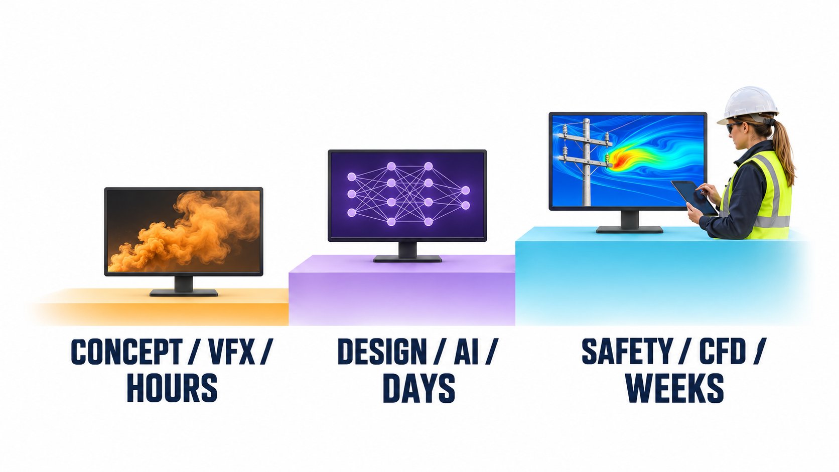
Concept, Design, Safety: three validation levels, each with its own method, time horizon, and decision domain.
Illustration: Three-level model of simulation methodology. Lo-Fi (VFX), Mid-Fi (AI Surrogate/PIML), Hi-Fi (CFD). Method follows the question, not the available budget[3][5][6] | AI-assisted illustration, not a product photo | VISORIC Newsroom | VISORIC GmbH
The decisive competency is not tool selection. It is the matching. Using a Level 1 result for a Level 3 decision is a methodological error, regardless of how capable the tool is. Conversely, applying CFD to every concept study wastes speed without gaining insight. The new core competency is: which question requires which validation depth?
| Level | Method | Time Horizon | Typical Questions | Not Suitable For |
|---|---|---|---|---|
| 1 Concept | Real-time visualization | Hours | Which geometry is promising? | Approvals, standards, certification |
| 2 Design | AI Surrogate (PIML) | Days | Which variant performs better? | Extrapolation outside training domain |
| 3 Safety | CFD (Navier-Stokes) | Weeks | Does the design comply with standards? | Replaceable by Level 1 or 2 |
The three-level model: method, time horizon, and decision domain at a glance.
Table: Editorial overview of the three validation levels with method, time horizon, typical questions, and exclusion criteria[3][5][6] | VISORIC Newsroom | VISORIC GmbH
- Level 1: Exploration and communication. Method: real-time visualization. Time horizon: hours.
- Level 2: Design decision. Method: AI Surrogate. Time horizon: days.
- Level 3: Safety validation. Method: CFD. Time horizon: weeks.
- Method follows the question, not the budget or the preferred software.
- The new core competency: correctly matching validation level to decision requirement.
The next chapter shows how this model applies in concrete industrial domains.
Three Domains, One Pattern: How the Model Works in Practice
Abstract models have a drawback: one can agree with them without drawing their consequences. Three industrial domains show what the three-level model means in concrete terms, how the methods interact, and where the limits lie in practice.
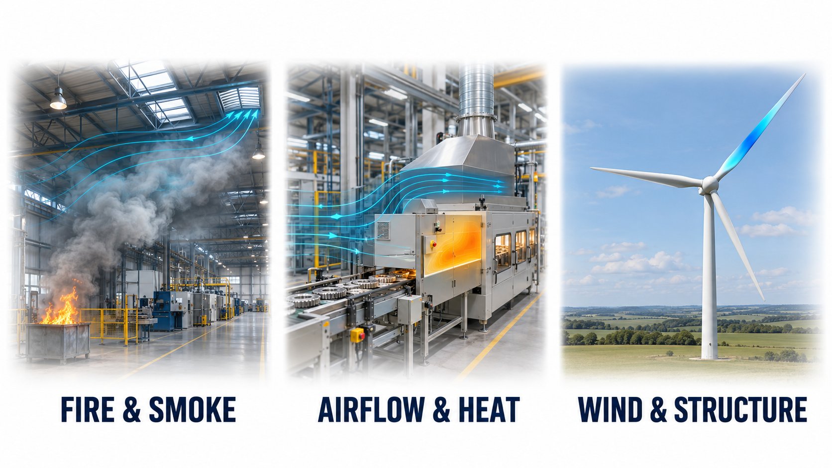
Fire protection and smoke propagation. In early fire protection planning for industrial buildings, Lo-Fi visualization enables rapid exploration of geometries, opening sizes, and hall layouts during the conversation. Architect and fire protection planner can explore different scenarios without computational overhead. In the design phase, AI Surrogates take over — trained on validated CFD data from real fire scenarios — delivering reliable design recommendations for ventilation openings, smoke extraction surfaces, and evacuation route geometries. CFD carries the permit application. No surrogate, no visualization replaces this step before authorities.
Thermal management in production. Temperature-critical manufacturing environments — clean rooms, die casting, electronics manufacturing — demand precise ventilation planning. Visualizations clarify during the concept phase which geometries are even viable. AI Surrogates enable iterative parameter studies in the design phase: ventilation geometries, heat source distribution, seasonal operating conditions. CFD validates the final design.
Wind loads for structures and installations. Wind turbines, industrial buildings, open-air installations: wind load calculation is central to structural planning, stability, and certification. Lo-Fi visualizations communicate the aerodynamic concept; AI Surrogates deliver reliable predictions for structurally relevant load cases in the design phase; CFD delivers the certification-ready calculation.
Fire protection, thermal management, wind loads: three domains in which the same pattern applies. Lo-Fi for concept, AI Surrogate for design, CFD for safety validation.
Illustration: Three-level methodology in practice: fire/smoke (fire protection planning), airflow/heat (production planning), wind/structure (wind load calculation)[4][7][8] | AI-assisted illustration, not a product photo | VISORIC Newsroom | VISORIC GmbH
The pattern is consistent. In all three domains, the same principle applies: Lo-Fi accelerates exploration, AI Surrogates enable informed design decisions, CFD validates what is safety-critical. The methods do not compete. They are stages of a validation chain.
| Domain | Lo-Fi (Concept) | AI Surrogate (Design) | CFD (Safety) |
|---|---|---|---|
| Fire Protection | Explore smoke propagation | Optimize ventilation design | Approval to EN standard |
| Thermal Management | Visualize airflow | Parameter studies for heat sources | Final design validation |
| Wind Load Calculation | Communicate aerodynamic concept | Structurally relevant load cases | Structural certification |
Three domains, one pattern: the three-level model in industrial practice.
Table: Editorial overview of the three-level methodology across three industrial domains[4][7][8] | VISORIC Newsroom | VISORIC GmbH
- Fire protection: Lo-Fi for the concept conversation, AI Surrogate for design recommendations, CFD for approval.
- Thermal management: visualization in the concept phase, parameter optimization with AI, CFD validation of the final design.
- Wind load calculation: communication (Lo-Fi), load case study (AI Surrogate), certification (CFD).
- The pattern is consistent across domains: method follows validation requirement.
- The methods are not competitors — they are stages of a validation chain.
The next chapter describes the pragmatic entry path for teams that want to start today.
Where to Start: An Entry Path in Five Steps
The question is no longer whether. The question is where. For teams that want to work with simulation methods in a structured way today, there is a pragmatic entry path. It does not begin with the tool. It begins with the question.
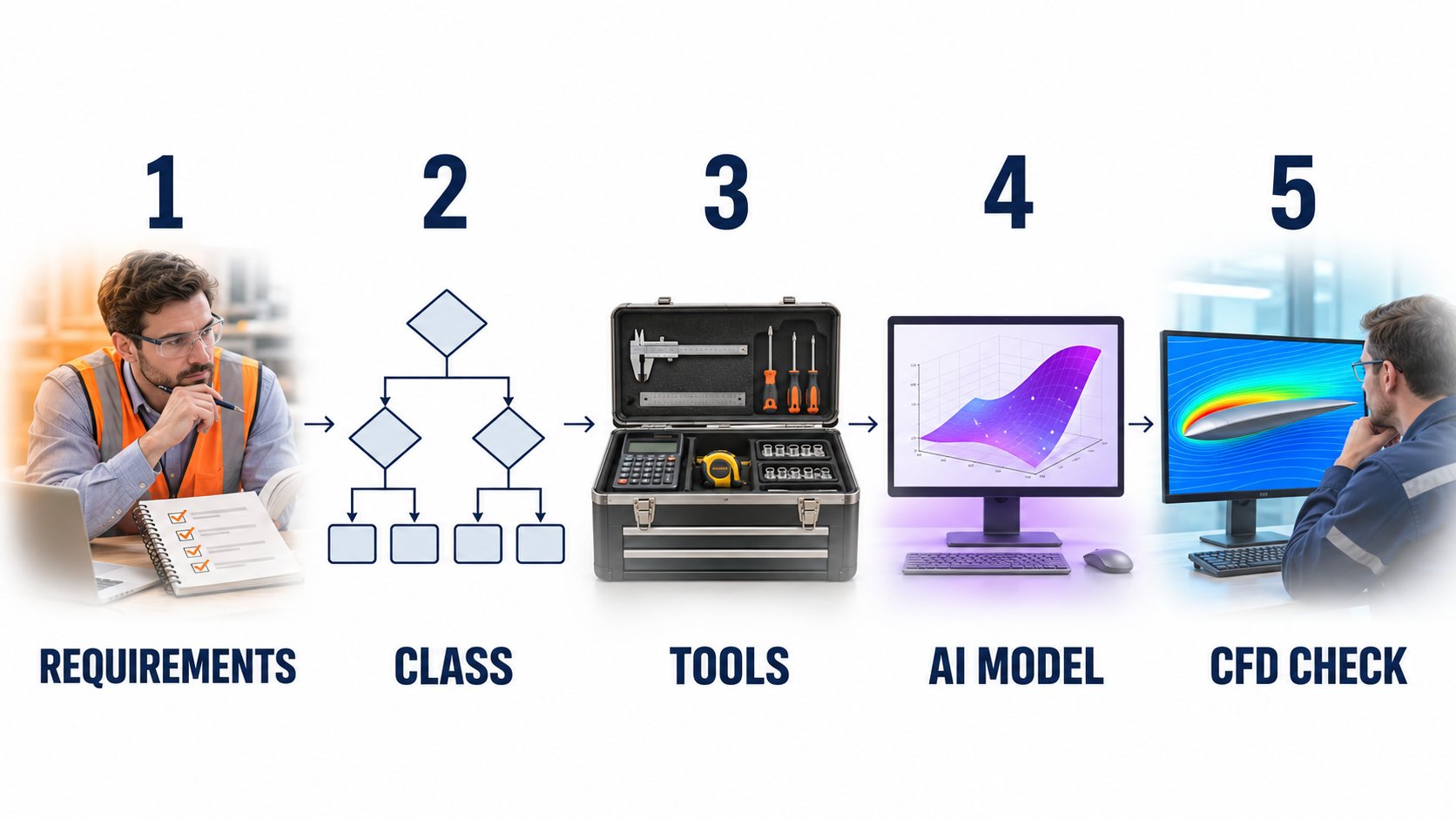
Step 1: Clarify requirements. Which decisions should the simulation support? Which standard, which authority, which approval body is involved? The answers determine which validation level is needed. Teams that skip this step choose the wrong tool for the wrong question.
Step 2: Determine the simulation class. Concept, design, or safety validation? Internally or externally relevant? Must the result be standards-compliant? The class determines the methodological framework.
Step 3: Consolidate data and tools. Which CAD data, geometry data, sensor data are available? For Level 2, this is decisive: an AI Surrogate is only as good as the CFD data it was trained on.
Step 4: Train or license an AI model. For Level 2 there are two paths: license an existing surrogate for the relevant use case, or train a custom model based on existing CFD data. The latter requires solid training data and is the entry point into long-term competency development.
Step 5: CFD check for safety-critical load cases. This step is not optional. It defines the boundary up to which approximation is permissible. Without it, the rehabilitation of approximation does not work.

Five steps, one principle: the entry into a structured simulation pipeline begins with the question, not the tool.
Illustration: Pragmatic entry path into a simulation pipeline. From requirements clarification through class determination, data foundation, and AI model training to CFD validation[2][5][7] | AI-assisted illustration, not a product photo | VISORIC Newsroom | VISORIC GmbH
The first step is not the tool. Teams that start with tool selection build on an unclear foundation. Teams that start with requirements clarification create the basis for a robust simulation strategy.
- Step 1: Clarify requirements. Derive the validation level from the decision requirement.
- Step 2: Determine the simulation class. Concept, design, or safety validation?
- Step 3: Consolidate data and tools. Training data foundation for Level 2 is decisive.
- Step 4: License an AI model or train it on CFD data.
- Step 5: CFD check for safety-critical load cases. Not optional, not negotiable.
The final chapter summarizes what the rehabilitation of approximation means — and what it does not.
What Remains: The Verdict Is Not Overturned — It Becomes More Precise
This article does not end with a resolution, but with a refinement. The decades-old verdict that classified approximation models as compromise was justified. It remains justified for every context in which physical validation is required. What changes is the space that precedes it.
That space was empty. AI fills it with a third method that is neither Lo-Fi VFX nor Hi-Fi CFD, but a data-driven middle level with a describable domain of validity. This accelerates development processes. It enables more iterations. And it makes simulation methodology accessible to teams that previously had no access to CFD resources.
What does not happen. CFD does not become obsolete. Navier-Stokes equations are not replaced by neural networks. Finite element meshes will not disappear. The difference is: they are deployed more purposefully, in the phases for which they are indispensable, rather than as the only available method for all phases.
What genuinely changes. The real shift is methodological, not technical. Teams working with simulation today need a competency that goes beyond operating a tool: the ability to correctly match validation levels, communicate results with their constraints, and consciously avoid the plausibility trap. This is the new methodological competency of the AI era.
The rehabilitation is deserved. Approximation models were considered second-best for decades, not because they were poor, but because their constraints were not quantifiable. AI changes that. Not by making approximations more precise, but by giving them a provenance: validated CFD data, a describable domain of validity, a quantifiable deviation. The compromise has become a method. That is the rehabilitation.

Three methods, one validation chain: Lo-Fi for concept, AI Surrogate for design, CFD for safety. The rehabilitation of approximation is strongest when applied with awareness.
Illustration: Three validation levels in one representation. Particle model (Lo-Fi), AI Surrogate Network (Mid-Fi), CFD flow lines (Hi-Fi)[3][5][6] | AI-assisted illustration, not a product photo | VISORIC Newsroom | VISORIC GmbH
- The decades-old verdict remains justified for every context in which physical validation is required.
- AI fills the empty space between Lo-Fi and Hi-Fi with a method that has a describable domain of validity.
- CFD remains indispensable for safety validation, standards compliance, and certification.
- The real shift is methodological: correctly matching and communicating validation levels.
- The compromise has become a method. Applied with awareness, that is progress.
The proof in motion is shown in the next chapter.
Lo-Fi in Action: Pressure Wave Simulation in Real Time
There is a difference between an argument and a proof. The following video shows a current real-time visualization system computing a pressure wave simulation at maximum voxel-grid resolution. It makes the abstract argument of this article visible: what these performance figures mean in visual impact, and why they must not be confused with CFD validation.
The system is called EmberGen, developed by JangaFX. It computes up to 67.1 million voxels in 35 milliseconds. And it is not a CFD tool.
Pressure wave simulation in real time: 67.1 million voxels in 35 milliseconds. What looks like physical precision is Lo-Fi at the concept level.
Video: EmberGen (JangaFX) pressure wave simulation, created by Naveed Ullah (@naveed_ullah600), published on LinkedIn/Instagram 2026. Not produced by VISORIC. Context: VISORIC Newsroom | VISORIC GmbH
The interesting thing is not the visual capability. The interesting thing is what the video says about the difference between visual persuasiveness and physical robustness. The simulation looks precise. It is not, in the sense of standards and certification. That is not a flaw. That is the defined scope of Level 1.
The question that counts is not: Can we simulate this? The question is: Which decisions does this result support — and which does it not?
- Current real-time visualization systems reach 67.1 million voxels in 35 milliseconds.
- Visually convincing at the concept level. Not physically validatable in the sense of standards and certification.
- That is the defined scope: exploration, communication, concept decisions.
- What matters is not the capability — it is the correct classification of the result.
Developing a Simulation Strategy: VISORIC as Your Concept Partner
Anyone who has read this far understands the mechanism. They know why approximation models were considered compromise for decades. They know the performance limits of modern visualization systems and their physical constraints. They understand the difference between Lo-Fi visualization, AI Surrogate, and CFD validation. And they know the three-level model that structures the matching of method to decision requirement.
The question is no longer whether. The question is: Which problem in your development process is the first one for which an AI Surrogate Model will make a difference in the next few weeks?
VISORIC supports product developers, planners, and Digital Twin architects in developing their simulation strategy: from mapping existing tools to the three-level model, through designing AI Surrogate pipelines, to visualizing simulation results for internal and external communication. Not as a platform provider selling a proprietary solver. Not as an agency converting a requirements analysis into a specification document. But as a concept partner who assesses technical feasibility, guides the right methodological decision, and proposes a development path that delivers visible results within weeks.
The VISORIC expert team from Munich combines over 15 years of experience in 3D, AI, and XR with hands-on expertise in Spatial Computing, real-time visualization, and Digital Twin architectures.
- Mapping existing simulation tools to the three-level model.
- Designing AI Surrogate pipelines based on existing CFD datasets.
- Visualizing simulation results for stakeholder communication and approval processes.
A well-defined first use case, a clearly scoped validation objective, and an existing CFD dataset can often be translated into a working AI Surrogate pipeline within a shorter timeframe than most teams expect — when the right expertise is in the right place.
Which simulation step in your development process would you most like to accelerate — and what has been holding you back?
Talk to the VISORIC expert team from Munich about simulation strategy, AI Surrogate Models, and the right entry into the three-level model. Together we turn your challenge into a precise, traceable next step.

15 years of experience in 3D, AI, and XR: the VISORIC expert team from Munich.
Image: © Ulrich Buckenlei | VISORIC Newsroom | VISORIC GmbH
Sources
- Naveed Ullah (@naveed_ullah600) — EmberGen pressure wave simulation, LinkedIn/Instagram, 2026
- JangaFX — EmberGen product specification: maximum voxel grid 1,024 × 1,024 × 64, GPU voxel throughput ~1.9 billion/second. jangafx.com
- Rajesh Ramaswami / Sazzad Hossain — LinkedIn comments on the EmberGen post by Ulrich Buckenlei, 2026 (primary source for topic framing)
- Brunton, S. L., Noack, B. R., Koumoutsakos, P. — Machine Learning for Fluid Mechanics. Annual Review of Fluid Mechanics, 52, 477–508, 2020
- Raissi, M., Perdikaris, P., Karniadakis, G. E. — Physics-informed neural networks: A deep learning framework for solving forward and inverse problems involving nonlinear partial differential equations. Journal of Computational Physics, 378, 686–707, 2019
- NVIDIA Modulus — Physics-Informed Machine Learning Platform for industrial CFD surrogates. developer.nvidia.com/modulus
- Siemens Simcenter / Ansys Fluent / COMSOL Multiphysics — CFD validation standards for industrial applications
- Gartner — Market Guide for Digital Twin Technologies in Manufacturing, 2024/2025
Contact Us:
Email: info@xrstager.com
Phone: +49 89 21552678
Contact Persons:
Ulrich Buckenlei (Creative Director)
Mobil +49 152 53532871
Mail: ulrich.buckenlei@xrstager.com
Nataliya Daniltseva (Projekt Manager)
Mobil + 49 176 72805705
Mail: nataliya.daniltseva@xrstager.com
Address:
VISORIC GmbH
Bayerstraße 13
D-80335 Munich